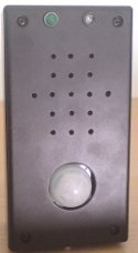
Motion Detector PIR Sensor
Project Specifications
- PIC:PIC18F25K20
- PIR Sensor:Sure DC-SS502
Circuit detect human movement in a space.
this project use PIC18F25K20 microcontroller to detect if the sensor change state and it will emit a sound from the speaker or piezo, the MCU also detect the voltage of the battery in the startup, the algorithm it´s very simple use an interrupt on change to detect the change on the PIR sensor.
| PIR Sensor | 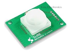 |
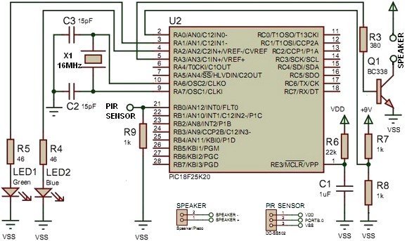
Circuit Diagram
Electronic Circuit Diagram - Motion Detector
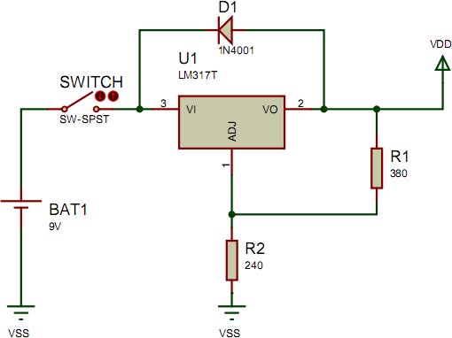
Power Supply
Power Supply Circuit Diagram - Motion Detector
VDD output is 3,3V, in this circuit 9V battery is connected to a IC L317T but input voltage can be 8 to 24V DC.
Calculate VDD value: VDD = 1,25 * (R2/R1+1)
Power On - when circuit start, a delay come to MCU generate a unknowed state, to avoid circuit malfunction, R6 and C1 make a RC delay filter, calculate delay with: τ = R * C
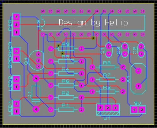
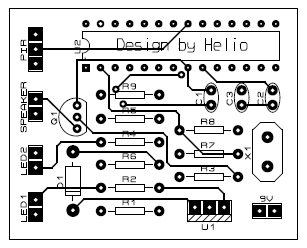
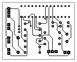
Motion Detector PCB
Layout
| Qt. | References | Value |
|---|---|---|
| 2 | R1, R3 | 380Ω |
| 1 | R2 | 240Ω |
| 2 | R4, R5 | 46Ω |
| 1 | R6 | 22KΩ |
| 3 | R7-R9 | 1KΩ |
| 1 | C1 | 1µF |
| 2 | C2, C3 | 15pF |
| 1 | U1 | LM317T |
| 1 | U2 | PIC18F25K20 |
| 1 | Q1 | BC338 |
| 1 | D1 | 1N4001 |
| 1 | BAT1 | 9V |
| 1 | LED1 | Green |
| 1 | LED2 | Blue |
| 1 | PIR SENSOR | DC-SS502 |
| 1 | SPEAKER | Speaker/Piezo |
| 1 | SWITCH | SW-SPST |
| 1 | X1 | 16MHz |
Top
Bottom
Source code files - Motion Sensor
Project Pictures

Speaker
Circuit have a 8Ω speaker but piezo can be used, transistor BC338 (Q1) is used because sound have low level and should be able to ear from a different division, with BC338 transistor β = 35. Transistor Ic can be calculate with this equation:
Vcc - (Rb * Ib) - Vbe = 0
Video
Author: Hélio Pereira