ESR Meter
Project Specifications
- PIC:PIC16F876A
- Processor Frequency:3.58MHz
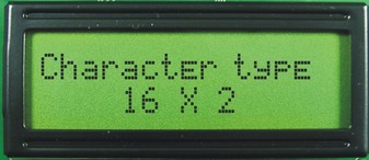
- Display Type:16 Character x 2
ESR Meter can read equivalent serie resistor in a capacitor inserted in circuit.
Use:The capacitance value of the device under test (DUT) is measured finding time taken to charge it to a particular voltage.
The ESR of DUT is measured subjecting it to a knowned current pulse and read voltage across it.
Calibration:
Take a good capacitor, around 100 or 1000 microfarads, and connect a small resistor, 10 or 5 ohms, in series with it. Connect to the meter and adjust that pot until the meter reads the resistance of that resistor. Repeat with other capacitors and resistors as a check on your calibration.
Limitations:Capacitors smaller than about 10 microfarads cannot be measured with ESR. Capacitance down to 10 picofarads may be measured, however devices with appreciable leakage cannot be measured at all for capacitance.
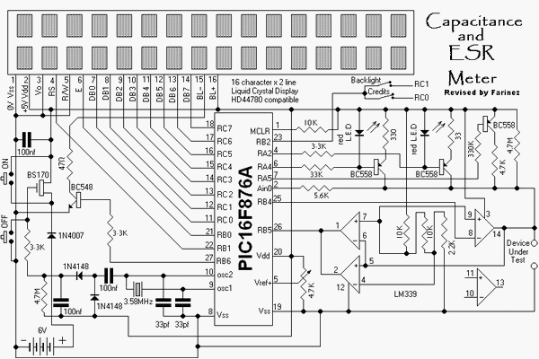
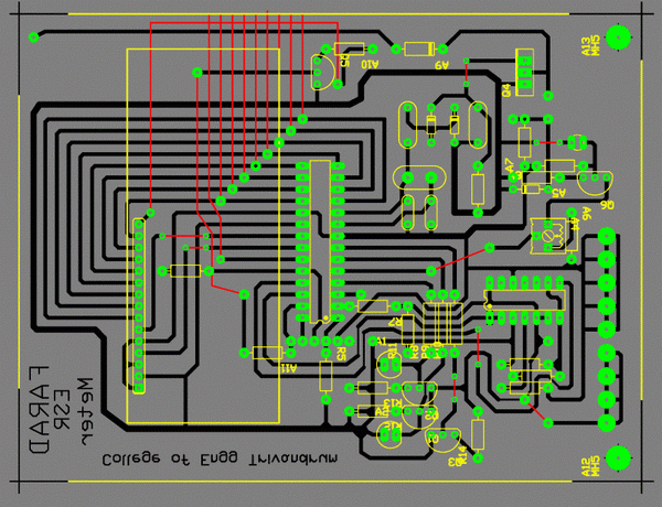
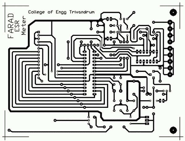
Circuit Diagram, PCB
Electronic circuit diagram - ESR Meter

PCB


* Not on scale
