TV Emitter
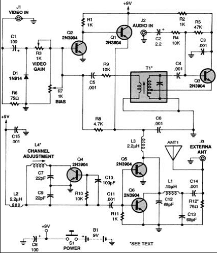
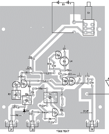
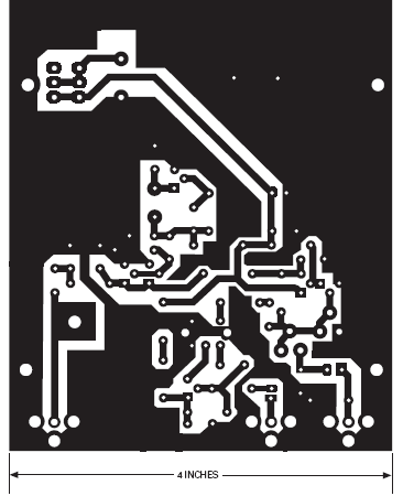
This TV transmitter circuit was designed to emit modulated RF signals with audio and video that may be received directly from the television. Is an analog emitter circuit.


- D1- 1N914 Sil. diode
- Q1- Q2-Q3-2N3904 transistors NPN
- R1- R2, R11- 1KΩ
- R3,R7- 1KΩ-Pot., horizontal.
- R4,R9,R10- 10KΩ
- R5- 47KΩ
- R6- 75kΩ
- R8- 4.7KΩ
- R12- 75Ω (2x 150 em parallel) (opcional)
- C1,C8-100μF, 16-V, elect.
- C2- 2.2--μF, 50-V, elect.
- C3,C6,C11,C14,c15-1nF, ceramics
- C7,C9-2.2-pF, ceramics
- C10-100-pF, ceramics
- C12, C13-68-pF, ceramics
- ANT1-Antenna
- B1 battery 9v
- J1,J3-Jack RCA, surface mount.
- L1- inductor 0.15-mini 0.15mH
- L2, L3-inductor mini de 2.2mH
- L4- 0.14- 0.24-μH adjustable, ferrite.
- S1-SPST, Push-Button, NO.
- T1- 4.5-MHz R Transformer
