Digital Clock with PIC16F84
Project Specifications
- PIC:PIC16F84A
- Processor Frequency:4MHz
- Range:0 to 24 Hours
- Timer Set:Up - Down Switch
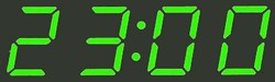
- Display: Hour:00-23 Minuts:00-59
- Power: External 6V D.C.
Clock count every second controled by hardware.
Adjustable time with SW1 and SW2 switches.
LED1 indicate seconds.
| Clock Display | 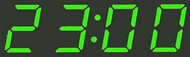 |
Circuit Diagram
Electronic Circuit Diagram - 12 or 24 Hours Clock
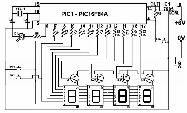
X1=4Mhz resonator.
Components
| Parts | Desc. |
|---|---|
| R1 – R8 | 100Ω |
| R9 - R13 | 10KΩ |
| C1 | 22pF |
| C2 | 22pF |
| D1 | LED |
| U1 – U4 | Common Cathode 7 Segment Display |
| Q1 – Q4 | C828 |
| XTAL1 | 4 MHz Crystal |
| IC1 | 7805 Regulator IC |
| PIC1 | PIC 16F84 OR PIC16F84A |
| SW1 -SW3 | Push to ON push button switch |